Creating a rechargeable SI Air chip
Introduction
My journey with using the SI Air chips began back in 2014 when I got my first chip. It was fairly early on but I wanted to make sure it was able to work with the O-Lynx radio controls I was making.
It wasn’t long before I began to acquire some more, this time to ensure the gear and software would also work for MTB events. I needed enough to be able to do the timing for a proper event and gain the experience needed to say what works and what doesn’t.
From the first event it was clear that Sportident had done a great job making an innovative, super power efficient and robust product that opened up many new possibilities. However, that first event, was also when I learnt that even new chips could fail with dead batteries. It’s not great to have to be in the position where you have to tell a rider that their days riding was not timed due to a dead timing chip.
I learnt how to change the batteries in the SI Air chips fairly quickly as being on the opposite side of the world meant I didn’t have much choice. However, like with when the chips were straight from the factory, it was still largely impossible to tell when a chip would fail, so timing an event was always filled with a certain amount of trepidation.
The chips themselves were wonderful, so if I could just overcome the battery issues, it would make timing the events so much less stressful, even enjoyable, as the riders love the instant feedback they give. Making them rechargeable seemed the only way to go as it would mean that for each event, I could guarantee each chip had just been fully juiced and would work for the whole event.
Now for the usual disclaimers. The following is my opinion and as such may contain errors, incorrect assumptions, or may simply not be the best way to do something. It is based on working with chips manufactured between 2014 and 2019. At the time of writing, I couldn’t see any specific details, but presume the following may void the Sportident warranty and guarantee.
Requirements
From the outset I didn’t want to reinvent or modify the chips. My focus was just on being able to take out the existing battery and put in something equivalent that was rechargeable.
Another requirement was that it didn’t risk interfering with the radio signals to and from the chip. This meant fanciful ideas of wireless charging were off the table, no matter how nice it sounds.
It was clear from the outset I would have to 3D print a new case for the chip to be able to provide some sort of connection for charging. I had gained some confidence from printing new tips for the chips when doing the battery replacements as the PETG plastic had proven light, waterproof and easily printed.
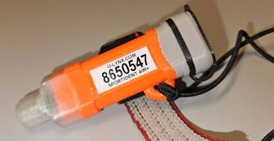
Size and weight also needed to be a consideration and I wanted something similar to the chips original body. The plastic design I arrived out is shown at the start of this article and available at..
https://www.printables.com/model/923090-replacement-case-for-siac-timing-chips
It also features a much needed elastic wrist loop mounting point that is large enough to make switching the chips to MTB events ( with don’t use the loop ) much easier.
Finding a battery.
Keeping the same size battery as the existing CR1632 would be ideal, so this pretty much meant the rechargeable lithium LIR1632 was the only option. It is also readily available on Aliexpress with the same PCB mounting legs.
e.g. https://www.aliexpress.com/item/32858911182.html?
Moving from non-rechargeable to rechargeable, the key differences are the voltage output and the nominal capacity. Rechargeable lithium cells usually have a nominal voltage of 3.7 volts compared to the original batteries 3.0 volts. The rechargeable cells also have a much lower nominal capacity of about 25mAh compared to over 100mAh for the non-rechargeable original battery. This capacity drop wasn’t an issue as the new batteries would still provide over 6 months of use and could be regularly recharged if needed.
The voltage is more of an issue as some of the components on the SI chips would definitely not like 3.7 volts connected up to them and as charging can take that voltage up to 4.2 volts, it would be dangerous to use a rechargeable cell directly in place of the existing battery. For example, the microprocessor used on the chip is rated at a maximum voltage of 3.6 volts.
Solving the voltage problem – option 1
The 3.3 to 4.2 volts of a rechargeable battery voltage needs to be dropped or regulated in some way so that ideally the voltage provided to the chip is kept in about the 2.5 to 3.3 volt range.
The simplest way to efficiently do this is to take advantage of the way a simple diode will drop 0.6 volts when connected in series. So the 4.2 volt max minus 0.6 volt should give a maximum voltage at the chip of 3.6 volts. However, the 0.6 volt drop rule doesn’t actually apply when the current drawn by the chip is super low as is the case with the highly efficient Sportident design and the actual voltage drop will be much less, putting the chip at risk. Its not all bad news for this simple method though as connecting 2 diodes in series will create a safe working voltage range the chip will be happy with.
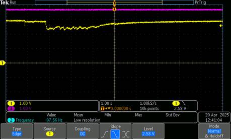
This is shown on the above scope capture. The purple line is the battery voltage at 3.7 volts. The yellow line shows the voltage at the chip when the chip is being punched. This sits at about 2.9 volts at idle, dropping to just over 2.3 volts at its lowest point. When fully charged to 4.2 volts the maximum voltage will be 3.3 V powering the chip. This falls within the microprocessor specs of 1.8 to 3.6 volts, but more importantly, in practical terms I have run about a dozen chips like this for at least 3 or 4 years without any problems.
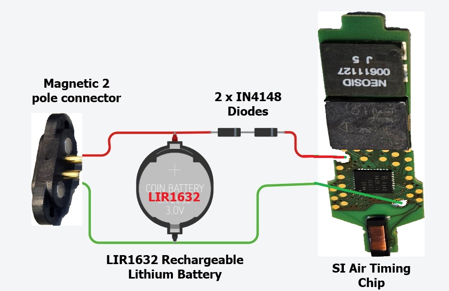
Figure 1: Connections for 2 diode solution
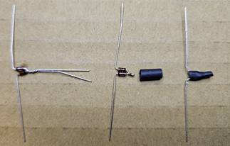
Figure 2: Making the 2 x diode and covering with heatshrink
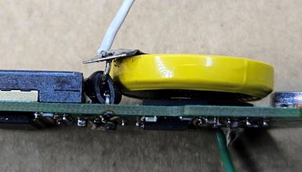
Figure 3: The 2 x diode connected between the battery tab and the circuit board
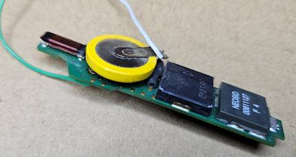
Figure 4: Showing the 2 x diode final position between the battery and the buzzer.
Solving the voltage problem – option 2
While the simple option works, its probably not the best technically correct solution, as the voltage to the chip does vary with how much power is being drawn. The battery is also directly connected to the charging connector, so there is a slim possibility of shorting out the battery if a metal object somehow became stuck across the connector’s terminals. With the small amount of power in the battery this is not hazardous, but may damage the battery.
Using a low drop out regulator is a more “correct” way of supplying the correct voltage to the timing chip. It is a more complicated solution as it does require a circuit board to be fitted to the chip to hold the components. A resettable fuse was also included in the circuit for that just-in-case of a short situation. This is the solution I ended up going with for my stock of timing chips.
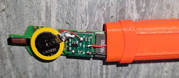
Figure 5: The regulator board is fitted to the top of the buzzer with double sided tape
The circuit boards are single sided, 0.8mm thick PCBs manufactured to be exactly the size of the buzzer at 11mm x 11mm. For the wires to the charging connector, I use the wires stripped out of old mouse cables which are small but have good flexibility.
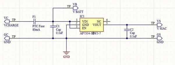
Figure 6: The circuit of regulated power supply. Note: the AP7354-30W5-7 is the regulator used ( 3.0 volt output )
Note : As the voltage supplied to the chip is now regulated to a constant value of 3.0 volts, testing the chips with a “SIAC test” station will not indicate the state of the battery. Instead, for testing, I use a USB tester fitted with a USB to Magnetic connector lead.
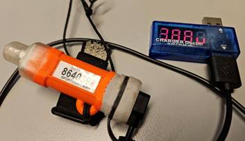
Figure 7: Using a USB voltage tester to read the battery voltage.
Not the complete solution
As with any project, there is always a wish list of what to do for the next version. Both option 1 and option 2 lack any sort of undervoltage cutout that should be part of a lithium battery circuit. Such a feature stops the battery discharging below a certain point e.g. 2.5 volts, which saves the battery from harm. E.g. if the Air chip develops a fault and discharges the battery too quickly, or if the chip is not used for a very long time.
In the absence of this within the current circuit, the counter measure is simply to charge up the chips at least every 6 months to a year, to ensure the voltage doesn’t degrade too much.
Charging connector
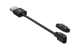
I looked at many connector options, but settled on using a magnetic connector as this meant …
- Connectors are waterproof.
- Minimal space required to mount so the case for the chip can still be kept small.
- Magnets ensure the connectors cannot be connected the wrong way around.
- Chips can be easily and quickly connected for charging.
While it may sound flawed to carry magnets on you hand when there is also likely to be a compass nearby, actual experience shows that the small magnets in the connector have no effect unless the compass is directly over the connector – something that is unlikely given they are usually carried on opposite hands. I’m not sure why the magnets have so little effect, perhaps something to do with the magnets being mounted with opposing poles in very close proximity, but while its something to be aware of, it means the pro’s of this type of connector far outweigh this negative feature.
The connector I use was originally sourced from www.element14.com but variations of it can also be sourced from aliexpress/Alibaba.
Element14 part number for connector and charging cable set is MP009330 or just the connector is MP009329.
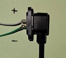
When fitting the charging connector into the chip end piece, solder the wires to the gold pins, then use a toothpick to spread some silicone sealant around these pins. The connector is held in place by M1.4 x 5 self tapping screws or similar.
e.g. https://www.aliexpress.com/item/1005003253490947.html?
To tell which pin is positive and negative, connect the charging lead as shown below, then solder the leads to the connector.
Charging
To keep the additions inside the timing chips to a minimum an external charger is used. I also didn’t want to reinvent a coin cell charger so settled on the CB06CRMA chargers available from Aliexpress.
https://www.aliexpress.com/item/4000899202509.html
By changing resistors these can be set to the requirements of the LIR1632 batteries. In my case charging voltage is set to 4.2V with a 20mA max charging current. A 3D printed case and an old USB A lead completes the single chip charger, while for the bigger 6 station charger I simply use multiple CB06CRMA chargers connected in parallel. The aliexpress page listed above should have details of changing resistors and connections required.
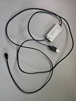
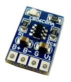
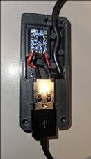
Figure 8: Single chip charger
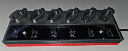
Figure 9: 6 Chip Charging station
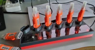
Figure 10: Charging station in use